Sparkworks · circuit reference
How the official Sparkworks spike-trap hallway works
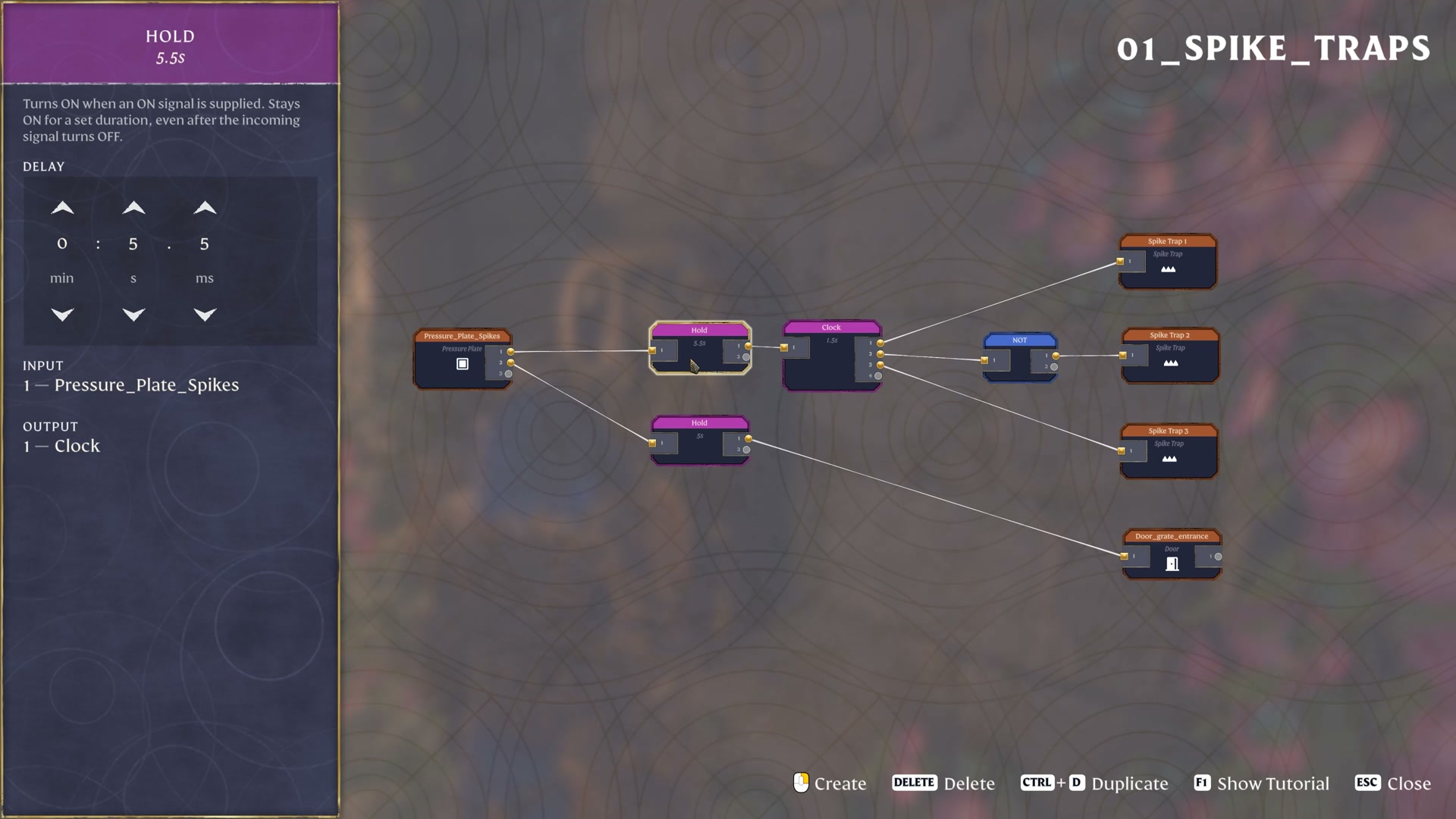
One pressure plate drives two branches. A 5.5-second Hold feeds a 1.5-second Clock: the Clock connects directly to spike traps 1 and 3, and through NOT to spike trap 2. A separate 5-second Hold controls the end door.
Based on the October 8, 2026 prerelease demonstration. Sparkworks is planned for October 15.
Read the official layout
 Open full-size image
 The trap branch: alternate the middle and outer spikes
Follow the upper wire from the pressure plate. The Hold keeps an ON signal for the shown 5.5-second duration, even after the incoming signal turns OFF. Its output feeds the Clock.
In the official explanation, the Clock signal inverts every 1.5 seconds. Its direct branch goes to Spike Trap 1 and Spike Trap 3. The other branch passes through NOT before reaching Spike Trap 2, so the middle spikes are not ON at the same time as the outer pair.
The useful pattern is a shared Clock plus one inverted branch. It makes the alternating groups easy for players to read. The developers also note that different periods can make a trap less predictable; the shown 1.5-second value is an example, not a required value for every hallway.
The door branch: why 5 seconds is different from 5.5
The second wire from the same pressure plate goes to another Hold. This one is set to 5 seconds and connects directly to the end door.
The official commentary says the door is kept open for 5 seconds. Its signal ends 0.5 seconds earlier than the trap branch because the gate needs time to close. These are two intentional settings on two separate Hold nodes.
Do not copy the trap branch’s 5.5-second setting onto the door merely to make the numbers match. The offset accounts for movement of the door in this particular example.
Read the sequence without guessing the initial phase
The pressure plate supplies the trigger.
Its wires start the trap branch and the door branch. They share an input, but they do not share a Hold node.
The trap branch holds its input for 5.5 seconds.
The Clock changes its signal every 1.5 seconds. The outer two traps receive the direct signal; the middle trap receives the inverted one.
The door branch ends earlier.
Its 5-second Hold gives the closing door a 0.5-second head start relative to the trap branch’s shown hold duration.
The demonstration establishes the connections and these durations. It does not establish a starting Clock phase, a retrigger rule, or that every spike becomes inactive when the Hold ends.
Compare the branches, not just the numbers
| Part of the graph | Shown connection or value | What to compare |
|---|---|---|
| Trap Hold | Pressure plate → Hold 5.5s → Clock | Keep this Hold on the trap branch. |
| Clock | 1.5s; direct to traps 1 and 3 | The outer pair follows the same signal. |
| NOT | Clock → NOT → trap 2 | Only the middle trap takes this inverted path. |
| Door Hold | Pressure plate → Hold 5s → door | The door has its own branch and shorter hold. |
What this pattern helps you design
Use the graph to understand a timed entrance that combines two alternating hazard groups with a separately timed door. Preserve the direct-versus-NOT split when you want the middle trap to alternate against the outer pair.
The demonstrated result is an alternating spike hallway with an end gate timed to start closing earlier. The screenshot does not provide physical spacing, component recipes or a complete setup from a new character. It also does not prove that ending the Hold resets the whole circuit. This reference explains the official wiring; it is not a release-tested construction tutorial.
Watch the connections being explained
- 1:27 — the spike hallway in action
- 1:37 — pressure plate, Hold and alternating traps
- 2:02 — the separate door connection
Source: Keen Games’ official Introducing Sparkworks demonstration, published October 8, 2026.