Sparkworks · circuit reference
How the official trapdoor bridge starts, alternates and stops
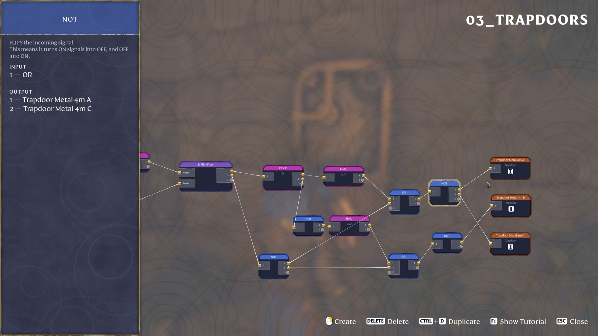
The official bridge uses start and end triggers around a D Flip-Flop, then a 3-second Clock and two 0.7-second Holds for its alternating trapdoor branches. The start trigger also passes through a 0.1-second Hold. A separate NOT branch joins the output OR nodes so the finish condition can stop the puzzle.
Based on the October 8, 2026 prerelease demonstration. Sparkworks is planned for October 15.
Keep the D Flip-Flop in the start/end path
The start trigger has two paths: one through Hold 0.1s to the D Flip-Flop’s Upper input, and one through OR to its Lower input. The end trigger joins that same OR.
This is why “start and end connect to OR” is only part of the explanation. The D Flip-Flop and the small 0.1-second Hold are visible parts of the actual graph. The Upper and Lower labels identify the ports shown; they do not establish a general priority rule for simultaneous input signals.
The official commentary says the puzzle starts at its trigger and turns off when the player reaches the end. The graph below retains the intervening nodes rather than inventing a simpler start/end circuit.
Inspect the original input connections
 Open full-size image
 Trace both timed branches and the shared stop branch
A D Flip-Flop output feeds Clock 3s. One Clock branch goes directly through Hold 0.7s; the other goes through NOT before another Hold 0.7s. A separate output of the D Flip-Flop goes through NOT and joins both output OR nodes.
Each output OR is followed by another NOT. The upper output group connects to Trapdoor Metal 4m A and C; the other connects to Trapdoor Metal 4m B. Keep the NOT nodes after the ORs as well as the NOT on the Clock branch: they occupy different places in the circuit.
The 3-second Clock interval is between ON/OFF changes, not a claim that a complete ON-plus-OFF cycle lasts 3 seconds. The 0.7-second Holds are the values shown in the example. The graph does not establish a first Clock phase or an exact timeline for every trapdoor movement.
Compare the output groups with the original graph
 Open full-size image
 The finish stops this puzzle, not the whole world
The official demonstration describes reaching the end as turning everything off in this jumping puzzle. That is the useful result of its start/end control path.
It does not establish a global Sparkworks reset, what happens on every later attempt, how state survives a reload or how D Flip-Flop ports behave under every combination of repeated inputs. Treat the finish connection as part of this particular demonstrated circuit.
This reference helps you identify the trigger, timing and output groups in the official example. It does not specify a construction recipe, platform spacing, a required jump skill or a complete from-zero placement procedure.
Watch the bridge and its finish condition
Source: Keen Games’ official Introducing Sparkworks demonstration, published October 8, 2026.